• The best technology

    The most advanced level of technical power
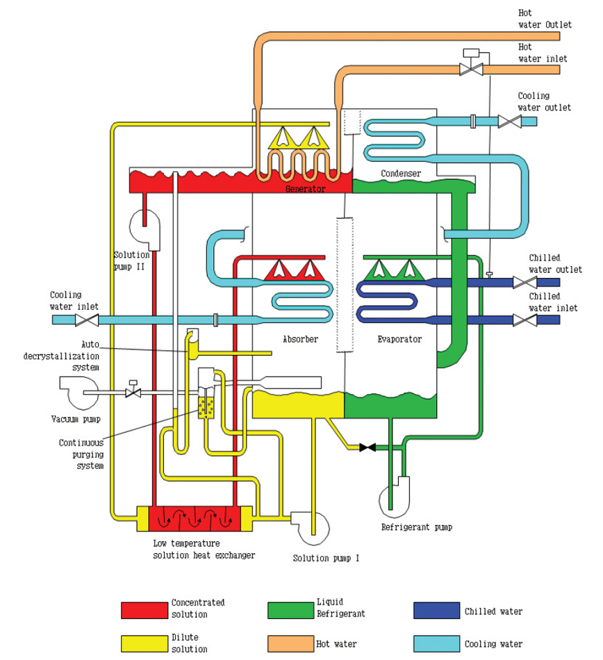
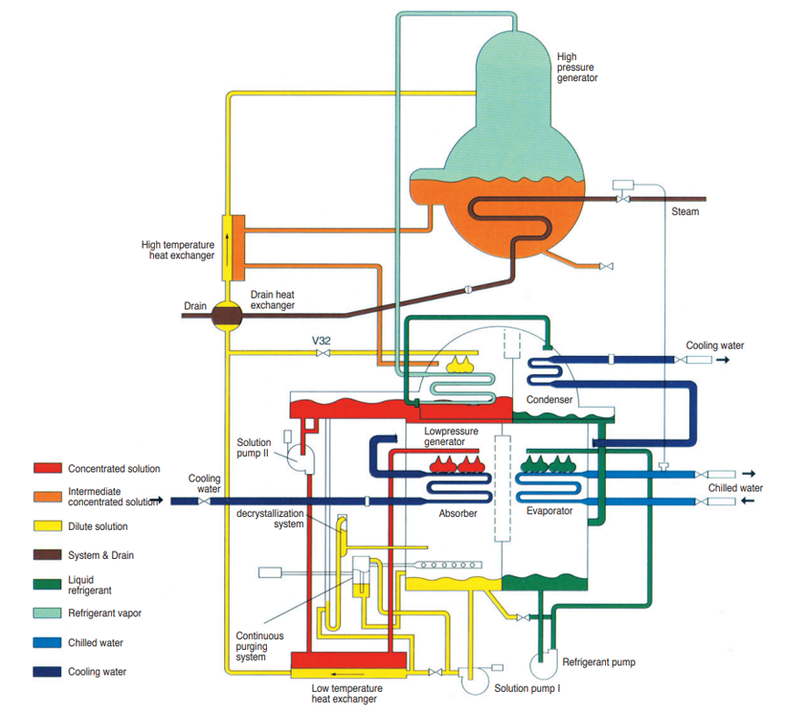
Product


01.

EVAPORATOR

  • Refrigerant enters the top of the lower shell or zone and is sprayed over the evaporator tube bundle. Heat from the liquid being chilled evaporates the refrigerant.
02.

ABSORBER

  • The refrigerant vapor is then drawn into the absorber side of the lower shell or zone. Here the vapor is absorbed by lithium bromide solution. Lithium bromide is, basically, similar to brine or salt water. But lithium bromide is a salt with an especially strong attraction for water. With the lithium bromide spray, it is as if hundreds of little sponges are sucking up the refrigerant vapor-called the "dilute solution" - which then collects in the bottom of the lower shell or zone.
03.

HIGH PRESSURE GENERATOR

  • The dilute solution is then pumped through the two heat exchangers where is preheated by hot concentrated solution from the generators. The heat exchangers improve the efficiency of the cycle by reducing the amount of gas/oil consumption required to heat the dilute solution in the high pressure generator. The dilute solution then flows to the high pressure generator shell (with a burner unit), beside the upper and lower shells. The dilute solution flows around the surfaces of the furnace tubes in the high pressure generator and is heated by gas combustion through the inside of furnace and tubes. The hot generator furnace and tubes allow the dilute solution to boil and it is further concentrated. Thus the dilute solution, straight from the high pressure generator is called the intermediate solution. The pressure in the high pressure generator is approximately 730mm Hg. The burner output is controlled by a valve in response to the cooling load required. Local superheat in the high pressure generator is avoided by the well distributed flow of the dilute solution between the shell and the outside of the furnace.
04.

LOW PRESSURE GENERATOR

  • The intermediate solution in the high pressure generator then flows to the upper shell or zone (low pressure generator & condenser) through the high temperature heat exchanger by gravity and pressure difference of both shells. The pressure in the upper shell is approximately one tenth that of the outside atmosphere, or 55mm Hg. The intermediate solution flows over the tubes and is reheated by refrigerant vapor-steam, generated previously in the high pressure generator. The refrigerant vapor has enough heat to make the solution more concentrated, releasing refrigerant vapor again at a lower pressure level and is drained to the condenser through a valve. The solution is now concentrated and flows through the heat exchanger, to the educator which is used to mix this solution with the re-diluted solution delivered from the solution pump. Then the mixed solution is sprayed on the absorber tubes.
05.

CONDENSER

  • The refrigerant flows to the condenser and is condensed. The liquid refrigerant, with the drained liquid from the low pressure generator, flows back to the lower shell, and is once again sprayed over the evaporator. The refrigerant cycle has been completed. Now the concentrated lithium bromide solution flows from the low pressure generator back to the absorber in the lower shell ready to absorb more refrigerant. Its cycle has also been completed.
Cooling Cycle
Features

High Peliability and Durability

  • Accumulated Technology for vacuum oreservation
    - Maintained high vacuum in shell due to high welding technology
    - Warranty of quality in figous test and inspection
  • No notice and no vibaration
    - Optimization of solution cycle
    - High efficiency of solution and refrigerant pump
    - Does not utilize a large motor compressor
  • Perfect safety protection devices
    - provides various safety devices and contril devices

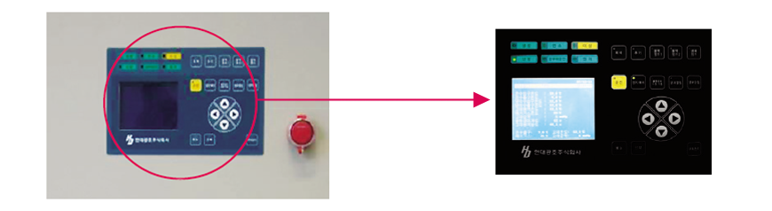
Easy Operation and Maintenance

  • High Function Control panel
    - PID control logic
    - Soft start-up and stoppage
    - Fully automatic control system such as stabilizer control, overried control and de-crystallization
    - Display detailed operating conditions, warning and trouble
  • Purging System
    - Qutomatic purging by Purge Tank pressure dectection
  • Automatic De-crystallization system
    - Protect crystallization by checking of solution concerntration in Generator
    - Reduce dilute operation time

High Effciency

  • Apply plate type heat exchanger
  • Solution and refrigerant spray system
  • Equipped with automatic purging system

Various application field

  • Recovery of waste heat from CHP
  • Recovery of waste heat from gas turbine ir gas engine
  • Recovery of waste heat from incinerator
  • Recovery of waste heat from combusion

Others

  • Ozone safe, cfc free, cooling requirements are met without chlorine based refrigerants.
  • Saving energy cost by using the waste heat.

Cooling Cycle